Clock Divider
Class Diagram
The UML diagram of Fig. 3 shows the overview of the class.
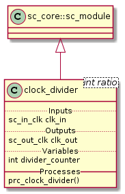
Fig. 3 Clock Divider Class Diagram
Class Description
-
template<int
ratio>
classclock_divider¶ Clock Divider module with clock division ratio
-
sc_core::sc_in_clk
clk_in¶ Input clock at normal rate
-
sc_core::sc_out_clk
clk_out¶ Output clock at rate of the input clock divided by ratio with the same duty cycle as the input clock.
-
int
divider_counter¶ Internal edges counter
-
sc_core::sc_in_clk
Structure
The structure of the clock divider is trivial since it has only one process.
Simulation Results
The simulation of the clock divider is just create 2 clock divider one with ratio 3 and other with ratio 4. Fig. 4 shows the result of the simulation.
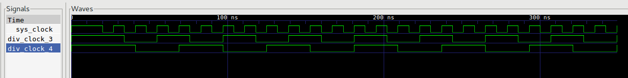
Fig. 4 Clock Divider Simulation Wave Result
Note
- div_clock_3 has \(\frac{1}{3}\) of the frequency of sys_clock
- div_clock_4 has \(\frac{1}{4}\) of the frequency of sys_clock
- div_clock_3 and div_clock_4 conserve \(50\%\) duty cycle