Serializer
Class Diagram
The UML diagram of Fig. 5 shows the overview of the class.
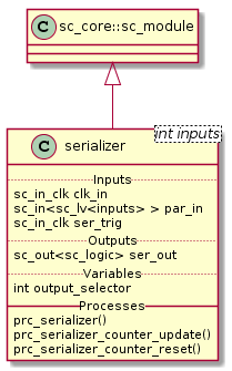
Fig. 5 Serializer Class Diagram
Class Description
-
template<int
inputs>
classserializer¶ Clock Divider module with clock division ratio
-
sc_core::sc_in_clk
clk_in¶ Input clock
-
sc_core::sc_in_clk
ser_trig¶ Trigger the serialization
-
sc_core::sc_out<sc_core::sc_logic>
ser_out¶ Serialized output
-
int
output_selector¶ Internal counter for select the bit index to forward to the output
-
void
prc_serializer(void)¶ Serializer main Process
Forwards the current bit to the ser_out. The current bit is calculated using output_selector. The serialization process starts with the ser_trig and ends when the last bit has been forwarded to the output. After forwarding the last bit the output is set to sc_logic(‘0’).
-
list
sensitivity¶ clk_in.pos(), ser_trig.pos()
-
list
-
sc_core::sc_in_clk
Simulation Results
The code of the test case of the serializer is shown below;
1 2 3 4 5 6 7 8 9 10 11 12 13 14 15 16 17 18 19 20 21 22 23 24 25 26 27 28 29 | ...
static const int inputs = 8;
SC_TEST(serializer) {
sc_clock sys_clock("sys_clock", clock_period, clock_duty, clock_start, false);
sc_signal<sc_logic> ser_out;
sc_signal<bool> ser_trig;
sc_signal<sc_lv<inputs> > par_in;
...
clock_divider<inputs> clk_div ("CLK_DIV");
...
serializer<inputs> serializer ("Serializer");
serializer.ser_out(ser_out);
serializer.clk_in(sys_clock);
serializer.par_in(par_in);
serializer.ser_trig(ser_trig);
par_in = sc_lv<inputs>("00000000");
sc_start(125, SC_NS);
par_in = sc_lv<inputs>("10010010");
sc_start(400, SC_NS);
}
|
Note
- The width of the serializer is \(8\)
- par_in[7:0] is set to \(0x92\) at \(125ns\)
Fig. 7 shows the result of the simulation.
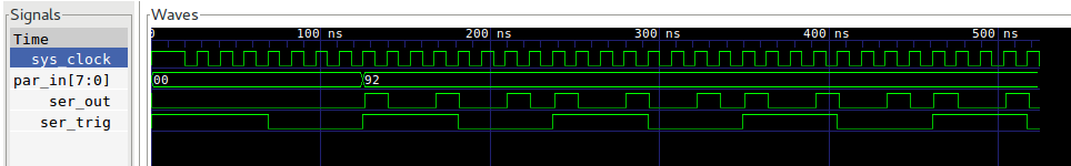
Fig. 7 Serializer Simulation Wave Result
Note
- ser_trig triggers the serialization to ser_out
- par_in[7:0] has a \(0x92\) and is the value that is actually serialized
- ser_out outputs the MSb first and the LSb at the end