Shift Register
Class Diagram
The UML diagram of Fig. 8 shows the overview of the class.
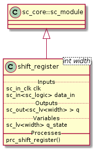
Fig. 8 Shift Register Class Diagram
Class Description
Structure
Fig. 9 shows the structure of the generic shift register. Our implementation doesn’t differ from the generic shift register.
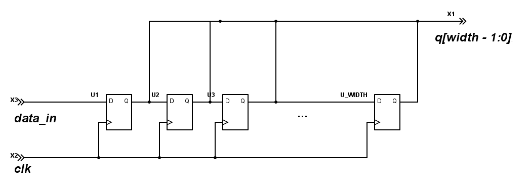
Fig. 9 Shift Register Circuit
Simulation Results
The code of the test case of the shift_register is shown below;
1 2 3 4 5 6 7 8 9 10 11 12 13 14 15 16 17 18 19 20 21 22 | ...
static const int reg_width = 5;
SC_TEST(shift_register) {
sc_signal<sc_logic> data_in;
sc_signal<sc_lv<reg_width> > register_state;
sc_clock sys_clock("sys_clock", clock_period, clock_duty, clock_start, false);
...
shift_register<reg_width> sregister ("ShiftRegister");
...
data_in = sc_logic('0');
sc_start(50, SC_NS);
data_in = sc_logic('1');
sc_start(100, SC_NS);
data_in = sc_logic('0');
sc_start(100, SC_NS);
}
|
Note
- data_in starts at sc_logic(‘0’)
- data_in toggles to sc_logic(‘1’) at \(50ns\)
- data_in toggles back to sc_logic(‘0’) at \(100ns\)
- Shift Register width is \(5\)
Fig. 10 shows the result of the simulation.
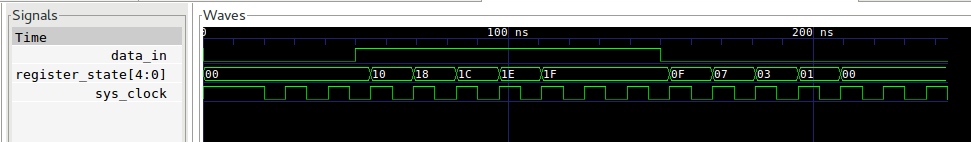
Fig. 10 Shift Register Simulation Wave Result
Note
- At \(50ns\) the shifting of sc_logic(‘1’) starts. The sc_logic(‘1’) is injected at the MSb.
- Between \(120ns\) and \(150ns\) the value of register_state[4:0] stays constant at \(0x1F\) because of the shift register’s width is set to \(5\).
- After \(150ns\) the shifting of sc_logic(‘0’) starts
- 5 clock cycles after \(150ns\) the register_state[4:0] is back to \(0x0\).