Convolution
Class Diagram
The UML diagram of Fig. 17 shows the overview of the class.
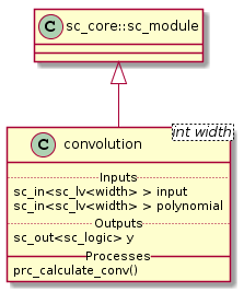
Fig. 17 Convolution Block Class Diagram
Class Description
Structure
The structure of this module comprises an array of \(input * memory\) and-gates to apply a bit-wise and between the polynomials and the input port. After applying the bit-wise and a xor reduce of all bits have to be applied. This implied \((input * memory) - 1\) xor-gates applying a xor operation to every bit of the result of the bit-wise and the result of the xor gate of the previous 2 bits (for the first 2 bits the xor-gate is simply apply to both).
Simulation Results
The code of the test case of the convolution is shown below;
1 2 3 4 5 6 7 8 9 10 11 12 13 14 15 16 17 18 19 20 21 22 23 24 25 26 27 28 | ...
static const int reg_width = 3;
...
SC_TEST(convolution) {
// create channels
sc_signal<sc_lv<reg_width> > shift_reg; //logic vector for shift register
sc_signal<sc_lv<reg_width> > generator_polynomial; //logic vector for shift register
sc_signal<sc_logic> conv_output; //logic output of output of convolution
// create module
convolution<reg_width> convolution("Convolution");
...
generator_polynomial = "101";
// start simulation
shift_reg = "100";
sc_start(100, SC_NS);
shift_reg = "110";
sc_start(100, SC_NS);
}
|
Note
- generator_polynomial is constant with value \(b101\)
- shift_reg starts with value \(b100\) and changes to \(b110\) at \(100ns\).
Fig. 18 shows the result of the simulation.
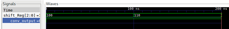
Fig. 18 Convolution Simulation Wave Result
Note
- Since the convolution is purely combinational no clock is needed.