Viterbi Encoder (with Lookup Tables)
Class Diagram
The UML diagram of Fig. 14 shows the overview of the class.
![@startuml
class sc_core::sc_module
class encoder_lkup<int output, int input, int memory> {
.. Constants ..
uint lookup_size = input << memory
.. Inputs ..
sc_in_clk clk
sc_in<sc_lv<input> > in
sc_in<sc_lv<memory * input> > polynomials[output]
.. Outputs ..
sc_out<sc_logic > out
.. Variables ..
sc_lv<memory * input> curr_state
sc_lv<memory * input> next_state_lkp[lookup_size]
sc_lv<output> output_lkp[lookup_size]
uint div_counter
__ Processes __
prc_state_trasition()
prc_update_output_lkup()
}
encoder_lkup -up-|> sc_core::sc_module
@enduml](../_images/plantuml-319c34dda4c7387686bad35986013511cd2a2a30.png)
Fig. 14 Viterbi Encoder with Lookup Tables Class Diagram
Class Description
-
template<int
output, intinput, intmemory>
classencoder_lkup¶ Viterbi Encoder with lookup tables
-
sc_core::sc_in_clk
clk¶ Input clock
-
sc_in<sc_lv<memory * input>>
polynomials[output]¶ Polynomials to convolve with
-
sc_out<sc_logic>
out¶ Serialized encoded output
-
sc_lv<memory * input>
curr_state¶ Current State value holder
-
sc_lv<memory * input>
next_state_lkp[lookup_size]¶ Next state lookup table. This is filled in by create_states_lkup.
-
uint
div_counter¶ Clock divider counter
-
sc_core::sc_in_clk
Note
next_state_lkp[lookup_size] and output_lkp[lookup_size] are filled using create_states_lkup and create_output_lkup respectively.
Structure
Fig. 15 shows the structure of the our Viterbi encoder implementation using lookup tables.
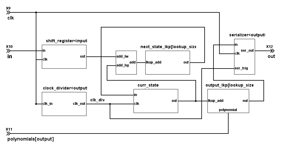
Fig. 15 Viterbi Encoder with Lookup Table Circuit
Simulation Results
The code of the test case of the viterbi_encoder_lkup is shown below;
1 2 3 4 5 6 7 8 9 10 11 12 13 14 15 16 17 18 19 20 21 22 23 24 25 26 27 28 29 30 31 32 33 34 35 36 37 38 39 40 41 42 43 44 45 46 47 48 49 50 51 52 53 54 55 56 57 58 59 60 61 62 63 64 65 66 67 | ...
static const int n = 2;
static const int k = 1;
static const int m = 4;
...
static const int output_size = n * (2* m - k);
SC_TEST(encoder) {
...
// Create signals
sc_signal<sc_lv<k> > in; //logic vector for shift register
sc_signal<sc_logic> out_0; //logic output of output of convolution
sc_signal<sc_logic> out_1; //logic output of output of convolution
sc_signal<sc_lv<m> > mem_bus[k]; //logic vector for shift register
sc_signal<sc_lv<m * k> > mem_bus_conv; //logic vector for shift register
sc_signal<sc_logic> serial_in_drv[n];
sc_signal<sc_lv<m> > polynomials[n];
sc_lv<output_size> expected_out = "11110111010111";
sc_lv<m> input_out = "1011";
// Create module
encoder<n, k, m> vencoder("ViterbiEncoder");
encoder_lkup<n, k, m> vencoder_lkup("ViterbiEncoderLKUP");
// Assign polynomials
polynomials[0] = "1111";
polynomials[1] = "1101";
...
vencoder.clk(sys_clock);
vencoder.in(in);
vencoder.out(out_0);
vencoder_lkup.clk(sys_clock);
vencoder_lkup.in(in);
vencoder_lkup.out(out_1);
// Output verification (11110111010111)
current_check_time = 220;
SC_EXPECT_AT(sc_logic('0'), out_0, current_check_time, SC_NS);
SC_EXPECT_AT(sc_logic('0'), out_1, current_check_time, SC_NS);
current_check_time += clock_period / 2;
for (int i = 0; i < output_size; i++) {
SC_EXPECT_AT(sc_logic(expected_out.get_bit(output_size - i -1)), out_0, current_check_time, SC_NS);
SC_EXPECT_AT(sc_logic(expected_out.get_bit(output_size - i -1)), out_1, current_check_time, SC_NS);
current_check_time += clock_period;
}
...
// Set the serial input to encode
for (int i = 0; i < m; i++) {
in = sc_lv<k>(sc_logic(input_out.get_bit(m - i -1)));
sc_start(2*clock_period, SC_NS);
}
in = "0";
sc_start(200, SC_NS);
}
|
Note
- Both implementation of Viterbi encoder are being tested the same way.
- Both encoders have the same input.
- The input is \(b1011\) and the expected encoded value \(b11110111010111\)
- The output is being verified with the
SC_EXPECT_AT
Fig. 16 shows the result of the simulation.
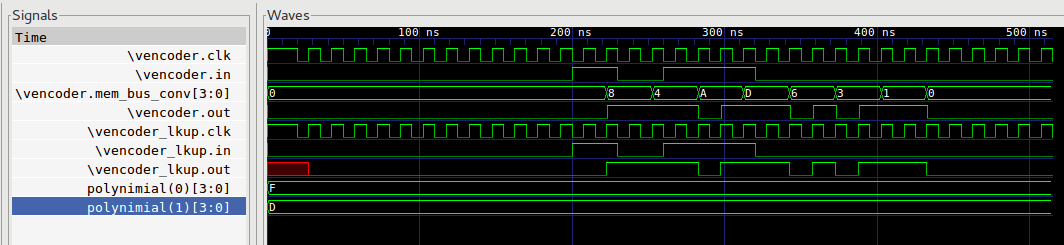
Fig. 16 Encoder Simulation Wave Result
Note
- At \(200ns\) the input starts to be in encoded. Both encoders have the same input.
- Just \(output\) cycles after the encoding starts.
- The encoded value’s MSb is transmitted first.
- Every in state has to be stable for \(output\) cycles.
- out_0 and out_1 have the same baudrate as the sys_clock
- out_0 and out_1 present the same behavior as expected
- out_0 and out_1 are set back to sc_logic(‘0’) after encoding is done (\(430ns\)).