Viterbi Decoder
Class Diagram
The UML diagram of Fig. 19 shows the overview of the class.
![@startuml
class sc_core::sc_module
class decoder_viterbi<int output, int input, int memory> {
.. Constants ..
const uint input_width = output * (2 * memory - input)
const uint states_num = input << (memory - 1)
const uint lookup_size = input << memory
const uint output_width = input_width / output
const uint MAX_STAGES = 2
.. Inputs ..
sc_in_clk clk
sc_in<sc_logic> in
sc_in_clk trigger
sc_in<sc_lv<memory * input> > polynomials[output]
.. Outputs ..
sc_out<sc_logic > out
.. Variables ..
viterbi_path_s<output_buffer_bit_size> trellis_tree_lkup[MAX_STAGES][states_num]
sc_lv<memory * input> next_state_lkp[lookup_size]
sc_lv<output> output_lkp[lookup_size]
uint curr_trellis_stage
uint serializer_count
bool decoding
bool serializing
.. Signals ..
sc_signal<bool> clk_div
sc_signal<sc_lv<output> > par_in
.. Events ..
sc_event shift_stage
.. Sub-modules ..
clock_divider<output> * clk_divider
shift_register<output> * shift_reg
__ Processes __
prc_decode_viterbi()
prc_shift_stage()
prc_update_output_lkup()
prc_serialize_output()
prc_decode_catch_trigger()
prc_decode_start_serializing()
-- Helpers --
uint get_metrics(uint val_0, uint val_1)
}
decoder_viterbi -up-|> sc_core::sc_module
@enduml](../_images/plantuml-d935cc649c916a361388322421bf69c83d08d225.png)
Fig. 19 Viterbi Decoder Class Diagram
Class Description
-
template<int
output, intinput, intmemory>
classdecoder_viterbi¶ Viterbi Decoder
-
sc_core::sc_in_clk
clk¶ Input clock
-
sc_in_clk
trigger¶ Decoding Trigger
-
sc_in<sc_lv<memory * input>>
polynomials[output]¶ Polynomials used for encoding
-
sc_out<sc_logic>
out¶ Decoded serial output
-
viterbi_path_s<output_buffer_bit_size>
trellis_tree_lkup[MAX_STAGES][states_num]¶ Trellis diagram lookup table. It only stores current stage and next stage. These 2 stages are the only ones needed at every calculation point in time.
-
sc_lv<memory * input>
next_state_lkp[lookup_size]¶ Next stage lookup table
-
uint
curr_trellis_stage¶ Overall current stage of the trellis diagram. It doesn’t only consider current and next stage. For every stage of the trellis diagram this value get incremented by 1.
-
uint
serializer_count¶ Bit selector counter for output serialization
-
bool
decoding¶ Flags that the Viterbi decoder is in decoding state
-
bool
serializing¶ Flags that the Viterbi decoder is in serializing state
-
sc_event
shift_stage¶ This event is trigger every time a stage of the Trellis diagram is completely calculated. Needed to switch to the next state, meaning assigning next state values to current state.
-
sc_signal<bool>
clk_div¶ Divided clock signal
-
clock_divider<output> *
clk_divider¶ Clock divider
-
shift_register<output> *
shift_reg¶ Shift register to parallelize the input
-
void
prc_decode_viterbi(void)¶ Decode a parallel input using Viterbi algorithm. This process calculate the Viterbi path for one stage of the Trellis diagram. The entire decoding is done when all the needed stages are calculated. The stage calculation is done every time the needed input bits are available, this increases the throughput of the Viterbi decoder, because it doesn’t have to have the entire input ready to start decoding.
-
list
sensitivity¶ clk_div.pos()
-
list
-
void
prc_shift_stage(void)¶ Moves the NEXT_STAGE values of the trellis_tree_lkup to the CURR_STAGE slot.
-
list
sensitivity¶ Dynamic sensitivity with shift_stage event
-
list
-
void
prc_update_output_lkup(void)¶ Build the output lookup table based on polynomials
-
list
sensitivity¶ polynomials
-
list
-
void
prc_decode_catch_trigger(void)¶ Catch the trigger for decoding. Initialize all needed structures for running the Viterbi decoding algorithm. Flags the decoding state after initialization.
-
list
sensitivity¶ trigger.pos()
-
list
-
void
prc_decode_start_serializing(void)¶ Catches the trigger for starting serialization. Flags serializing state and unflags the decoding state.
-
list
sensitivity¶ trigger.neg()
-
list
-
uint
get_metrics(uint val_0, uint val_1)¶ Calculate the metrics between two values.
Parameters: - unit val_0 – First value
- unit val_1 – Second value
Returns: Metric value
-
sc_core::sc_in_clk
Simulation Results
The code of the test case of the viterbi_decoder is shown below;
1 2 3 4 5 6 7 8 9 10 11 12 13 14 15 16 17 18 19 20 21 22 23 24 25 26 27 28 29 30 31 32 33 34 35 36 37 38 39 40 41 42 43 44 45 46 47 48 49 50 51 52 53 54 55 56 57 58 59 60 61 62 63 64 65 66 67 68 69 70 71 72 73 74 75 76 77 78 79 80 81 82 83 84 85 86 87 88 89 90 91 92 93 94 95 96 97 98 99 | static const int n = 2;
static const int k = 1;
static const int m = 4;
...
static const int output_size = n * (2* m - k);
SC_TEST(decoder) {
// Create signals
sc_signal<sc_logic> in;
sc_signal<sc_logic> out;
sc_lv<4> expected_out;
sc_signal<sc_lv<m> > polynomials[n];
sc_lv<output_size> in_bus;
sc_signal<bool> trigger;
uint current_check_time;
expected_out = "1011";
// Create module
decoder_viterbi<n, k, m, out_buff> vdecoder("ViterbiDecoder");
// Assign polynomials
polynomials[0] = "1111";
polynomials[1] = "1101";
...
for (int i = 0; i < n; i++) {
...
vdecoder.polynomials[i](polynomials[i]);
}
vdecoder.clk(sys_clock);
vdecoder.in(in);
vdecoder.out(out);
vdecoder.trigger(trigger);
...
// Output verification (1011)
current_check_time = 312;
SC_EXPECT_AT(sc_logic('0'), out, current_check_time, SC_NS);
current_check_time += clock_period;
for (int i = 0; i < m; i++) {
SC_EXPECT_AT(sc_logic(expected_out.get_bit(m - i -1)), out, current_check_time, SC_NS);
current_check_time += clock_period;
}
current_check_time = 1010;
SC_EXPECT_AT(sc_logic('0'), out, current_check_time, SC_NS);
current_check_time += clock_period;
for (int i = 0; i < m; i++) {
SC_EXPECT_AT(sc_logic(expected_out.get_bit(m - i -1)), out, current_check_time, SC_NS);
current_check_time += clock_period;
}
trigger = false;
in = sc_logic('0');
// Trigger and receive the correct data
sc_start(50, SC_NS);
trigger = true;
in_bus = "11110111010111";
for (int i = 0; i < output_size; i++) {
in = in_bus[output_size - i - 1];
sc_start(clock_period, SC_NS);
}
in = sc_logic('0');
sc_start(50, SC_NS);
trigger = false;
sc_start(490, SC_NS);
// Trigger and receive the data with errors
in_bus = "01100111010110";
trigger = true;
for (int i = 0; i < output_size; i++) {
in = in_bus[output_size - i - 1];
sc_start(clock_period, SC_NS);
}
in = sc_logic('0');
sc_start(5, SC_NS);
trigger = false;
sc_start(500, SC_NS);
}
|
Note
- At \(50ns\) the correct data starts coming in.
- At \(815ns\) the data with 3 inverted bits starts coming in.
Fig. 20 shows the result of the simulation for the correct data being received and Fig. 21 shows the results of the simulation for the data with 3 inverted bits.
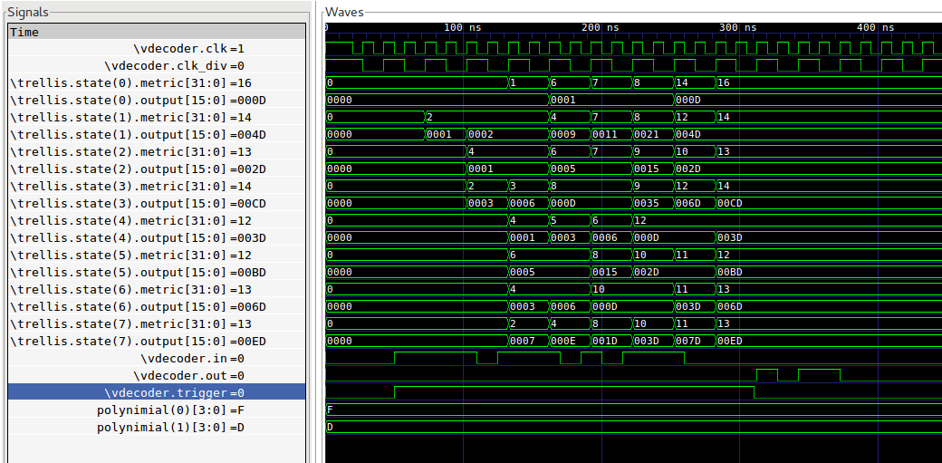
Fig. 20 Decoder Simulation Wave Result
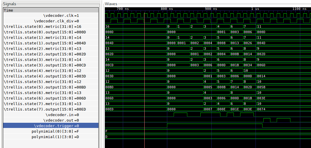
Fig. 21 Decoder Simulation With Errors Wave Result
Note
- At \(312.5ns\) the decoding of the correct data starts going out.
- The decoding of the correct data is \(b1011\).
- At \(1017.5ns\) the decoding of the data with errors starts going out.
- The decoding of the data with 3 inverted bits is \(b1011\).
- The decoding is successful even with errors.
- The metric of best path (with higher metric) passing through every of the \(8\) states can be seen in the trellis.state(0-7).metric[31:0].
- The possible output of best path (with higher metric) passing through every of the \(8\) states can be seen in the trellis.state(0-7).output[15:0]